Introduction to the Address Resolution Protocol (ARP)
Table of Contents
Intro
In my experience, computer networking is often seen as a mystical field by many developers and software engineers. This always seemed odd to me - but - I am an odd person. I’ve always found the ins-and-outs of computer networking interesting and the way I learned the fundamentals of network protocols was by messing with them through programming. Upon entering my career, I soon realised that a lot of software engineers don’t touch these lower-level networking concepts and even find them intimidating.
So - My aim here is to explain to you some of the concepts of lower-level network protocols by giving you an introduction to how address resolution works in IPv4 networks. Then I want cement that in you by teaching you how to mess with that process by constructing malicious packets from scratch in C. Doing all that in a single article would probably be quite an overwhelming read, so I have divided this in two articles.
In this first article I will be giving you an introduction to addressing in computer networks, the internet protocol suite and the address resolution protocol. For the second part I will be walking you through how to exploit ARP by writing a toy C program which will require an understanding of the C programming language.
Thank you Kiran Ostrolenk for reviewing and helping me edit this article.
Packets and addressing
Let us start with the lowly Network Interface Controller - also called a NIC, a network interface or simply just ‘interface’. A NIC is a piece of hardware that connects to some sort of media (such as a copper cable or 2.4Ghz wireless) and allows you to access a computer network. NIC examples include an ethernet port on your motherboard or the wireless card in your smartphone or laptop. NICs transmit and receive units of information called ‘frames’ - but you probably call them by the generic term ‘packets’.
The beginning of a frame/packet contains information about which interface/NIC the frame is meant for. When an interface receives a frame it is only concerned about whether the destination MAC address in the frame is its own (most of the time), it accepts it if it is - and discards it if it isn’t. So when a host constructs a packet, the destination MAC address in the frame needs to be filled so that the target interface will accept it. So how do hosts find the MAC addresses of other hosts?
Let’s slow down a little - and discuss what a packet and a frame actually is. ‘Packet’ is quite a loosely used term these days (and I will indeed use the term quite loosely in this article) but abstractly, it refers to the units of data transmitted in packet switched networks. In TCP/IP terms, packets are more specifically Protocol Data Units (PDUs) that contain IP headers. Frames are PDUs encased in an data-link layer addressing information such as ethernet frames.
What are headers? Headers are sort of like the lines of an address on a letter. When you want to send a letter, you usually address it to a specific recipient, at a specific location. You post the letter in your local letterbox and it gets collected by the postman. They take it to a local post depo and it gets sorted according to its destination address. If the destination address is relatively far away (such as in a different city or country) it gets routed to other postal facilities before it is distributed in the recipients local mail service.
Addressing and routing in computer networks works just like this as well. Frames have headers that contain the addressing information needed to route them to their destinations. Packets are routed to multiple points according to their destination IP address and eventually reach their addressee (much like the postal system).
- Protocol addresses (also called logical addresses) are IP addresses. There are designated private IP addresses that are used only to identify interfaces in private local networks (LANs). And public IP addresses which can be used to host endpoints on the internet. IP addresses are typically tied to a certain NIC/interface and thus a certain MAC address. An interface can have multiple IP addresses associated with it. A interface’s IP addresses are not forever and can be changed anytime.
- Hardware addresses (also called physical or layer-2 addresses) such as MAC addresses are only used identify hosts on the local network. MAC addresses are usually forever and don’t change - NICs have MAC addresses baked into them when they are manufactured. A interface’s IP address may change but its MAC address (usually) never does. In our postal system analogy you can think of this as your name as the addressee. You may move house (just like a host may have a change in IP address) but you don’t usually change your name when you move. And your name also usually uniquely identifies you within your household, just like a MAC address identifies an interface on the LAN.
The reason I say ‘usually’ when talking about MAC addresses never changing is because it has become increasingly common for devices such as smartphones to fabricate a false MAC address whenever they change networks. This feature exists to prevent people from tracking devices across computer networks by their MAC addresses. See MAC Address randomisation for more info.
Each packet is a unit of data that is wrapped in layers of addressing information (usually found at the very beginning of the packet). There’s a keyword there - packets are layered. At the bottom most layer is addressing information that identifies a host on a LAN, the data-link layer. In the next layer up we find addressing information that specifies a network layer address, such as an IP address. As we discussed, MAC addresses are only used to refer to hosts on the LAN whereas IP addresses may specify a host on the internet (public addresses). At which point it is up to a router to use the network-layer addressing information (IP address) in the packet’s headers to pick the best path for to its destination. Much like it is up to the postal service to read the addressing information on your letter and get it to its destination.
To summarise this section a little:
- MAC addresses are used to identify hosts/interfaces on the LAN. They usually never change.
- IP addresses are used to identify both hosts on the LAN and hosts on different networks.
- Both these addresses are kept in data structures called ‘headers’ at the beginning of every packet.
- Headers are used by network devices to know where to send packets next.
TCP/IP - The internet protocol suite
We’ve talked a lot about ’layers’ so before we proceed further, it will probably help to have some understanding of the internet protocol suite better know as ‘TCP/IP’. TCP/IP models the protocol layers that are used in computer networks. Each layer theoretically acts independently of the other layers. In the TCP/IP model we have 4 distinct layers, I’ll discuss them from the bottom up:
+-+-+-+-+-+-+-+-+-+-+-+-+-+-+-+-+-+-+-+-+
|           Application Layer           |
+-+-+-+-+-+-+-+-+-+-+-+-+-+-+-+-+-+-+-+-+
|             Transport Layer           |
+-+-+-+-+-+-+-+-+-+-+-+-+-+-+-+-+-+-+-+-+
|         Internet/Network Layer        |
+-+-+-+-+-+-+-+-+-+-+-+-+-+-+-+-+-+-+-+-+
|     Data-Link/Network-Access Layer    |
+-+-+-+-+-+-+-+-+-+-+-+-+-+-+-+-+-+-+-+-+
- Network Access / Data-Link layer: The data-link layer (also called link-layer, network access layer) is the layer concerned with moving data in and out of the physical link on a network. At this layer we have NICs, the Ethernet II frame and hardware addressing such as MAC addresses.
- Network Layer: This layer is concerned with logical network addressing and network layer transmission. This is the layer at which the IP headers exist and is used for routing packets outside of the network. An example of a network-layer device is a router. When routers receive packets, they strip off the ethernet frame, observe the destination IP address contained in the IP header and then consult their routing tables to decide which interface is best path to the packet’s destination. It then encapsulates the packet in a new ethernet frame and transmits it. They aren’t concerned with the actual payload/contents of the packet - just the IP header so they know where to send it.
- Transport Layer: This is where TCP segments and UDP datagrams live. This layer is concerned with the transport of traffic to specific services and applications (which are designated by port numbers) on a host and the state of the connections to those services. For example the TCP handler will pass packets with a destination port of
80to the socket bound to port80- which is reserved for use in HTTP. The kernel will handle the state of the TCP connection for the application (i.e. re-assembling packets in the correct order, etc). - Application Layer: This is the most abstract layer. Here there may be an application layer protocol such as HTTP or even just a binary blob payload in some ongoing TCP connection. The application layer is usually handled in userland. For example, a webserver is a userland application that will open sockets and bind them to port
80and433and listen for incoming TCP connections - handled by the kernel.
NOTE: The term ’layer-2’ to describe the data-link/network-access layer comes from the OSI model, which is another framework for networking that is commonly used in discussion. It defines 7 layers with the bottom most layer being the ‘physical layer’ (Which concerns itself with how PDUs are encoded on physical wires such as 10BASE-T or RS-232 serial), which is not present in the TCP/IP model. The next layer above the physical layer is the data-link layer and is thus the second layer or ’layer-2’.
In theory each layer is handled independently of the other layers. A NIC or a layer-2 switch doesn’t strictly need to concern itself with the concept of IP addresses. A router doesn’t need to concern itself with the logistics of an ongoing TCP session. And the kernels TCP handler doesn’t need to care about the application-layer payload. In packet transmission each layer is constructed from the top-down (starting with the application layer) and the sort-of wrapped in a header for the next layer. This is called ‘encapsulation’.
Let’s use a HTTP request as an example:
- When you send a HTTP request, the HTTP payload (the application layer) is built in userland (by a web browser for example), where it supplied to a call to
send(2)and is copied into a buffer in kernel space. - The kernel then encapsulates the HTTP request in a TCP segment (transport layer)
- It then encapsulates the TCP segment in an IP header (network layer) with a source IP address of the transmitting interface and the destination IP address of the target webserver.
- The device driver for the NIC will then encapsulate the packet in a layer-2 ethernet frame with the source MAC address of the transmitting NIC and the destination MAC address of the webserver and then place it in a queue to be transmitted.
NOTE: Packets are constructed and encapsulated working down through the TCP/IP model, and then received and decapsulated working up through the model. In the example above, the HTTP header is created, then the TCP segment, then the IP header and then the ethernet frame - and then it is transmitted. The interface on the receiving host accepts the packet, strips off the ethernet frame and passes it to the kernels IPv4 handler where the IP header is processed and stripped off and passed to the TCP handler. The TCP handler processes the segment and strips it off before passing the application-level payload to the call to
recv(2)in the webserver.
You may have noticed that the packet includes a destination IP address and a destination MAC address. Why is this? Remember that MAC addresses exist at the data-link layer and only identify a host on the LAN. The webserver we’re speaking to (google.com for instance) probably lives on a host on another network somewhere in the internet. So in this case - the destination MAC address in the ethernet frame is actually the MAC address of the default gateway/router on the LAN. The gateway will receive the frame and use the addressing information in the IP header to route the packet on its way. But how does the kernel know the destination MAC address of the gateway at all? How does it know the MAC address of any host on the LAN? On an IPv4 network, this is done through the Address Resolution Protocol (ARP).
Summary of this section:
- Computer networking works in layered models. One such model is the TCP/IP model which defines 4 distinct layers.
- The application layer contains protocols that are typically handled in userland by applications such as web browsers.
- The transport layer is concerned with the transportation of traffic to specific services and applications and is handled in the kernel.
- The network layer is concerned with logical network addressing and inter-network routing and is handled in the kernel.
- The data-link/network-access layer is concerned with the transmission of frames across the physical media. Ethernet frames and MAC addresses exist at this layer.
The Address Resolution Protocol (ARP)
As discussed, NICs exist at the link-layer, they need not understand the concept of an network-layer address such as an IPv4 address. When a host needs to send network-layer messages to another host, it needs to resolve the logical destination address to a physical hardware address. This is so it can encapsulate the IP packet in an Ethernet frame with a proper destination MAC address. IPv4 hosts achieve this through Address Resolution Protocol, ARP.
Earlier we said that when an interface receives a frame, it is only concerned whether or not the destination MAC address is its own. This was a small lie. While most of the time this is all an interface will accept, it will also accept frames addressed to the all-1s MAC address ff:ff:ff:ff:ff:ff called the broadcast address.
NOTE: NICs will also accept frames with multicast destination addresses if they are members of that multicast group. Additionally NICs that support promiscuous mode can accept any frame they receive regardless of the destination address.
All interfaces on a LAN will accept frames addressed to broadcast MAC address. So - knowing this, this is basically how ARP works:
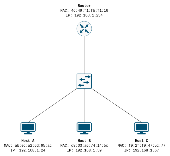
- Host A wants to send traffic to IP address
192.168.1.67. So it first checks it’s routing table to see if the target IP address is on a subnet it can reach directly through one if its interfaces. It is - Host A has an IP on the192.168.1.0/24subnet so it knows that address should be reachable through that interface. - Host A constructs a ARP request, the request header contains the IP address and the MAC address of the transmitting interface. The requested IP,
192.168.1.67is inserted into the destination protocol/IP address in the ARP request header. The destination hardware/MAC address is meaningless in an ARP request (as we don’t know it) and is ignored. The request is encapsulated in an ethernet frame to the broadcast addressff:ff:ff:ff:ff:ff, and the interface’s own MAC address is used as the source hardware address. That is to say - the source MAC address appears twice in an encapsulated ARP packet, once in the ARP header and once in the ethernet frame.
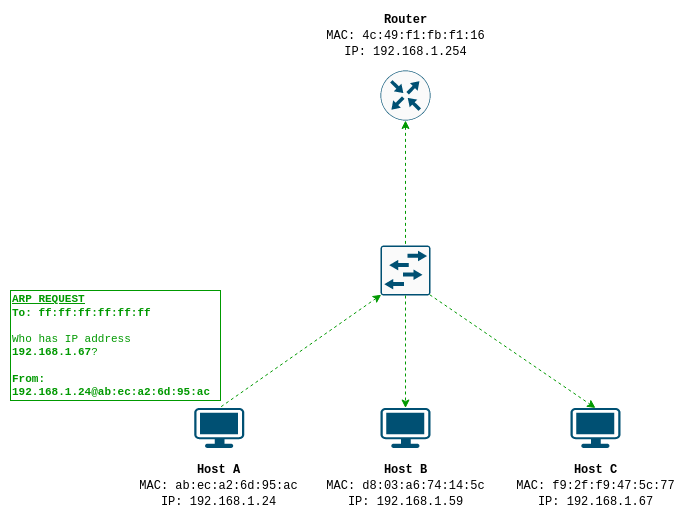
- All interfaces on the LAN receive and accept the frame from Host A, decapsulate it and hand it off to their ARP handlers. However, only Host C, the host with the requested destination IP address in the ARP header, replies to Host A. Host C stores the source addressing information Host A sent in its ARP cache, and then sends Host A an ARP reply message. The ARP reply has Host C’s hardware address and protocol address in the ARP header as the source, and Host A’s hardware address IP address as the destination.
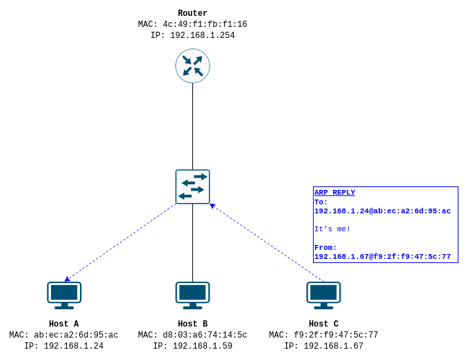
- Host A receives the ARP reply and stores Host C’s address information in it’s ARP cache. Now both Host A and Host C are aware of each other’s physical to logical address mappings.
Both hosts will cache the information they received in the OS’ ARP cache/table so that the hosts don’t need to perform the ARP dance for every time they want to transmit a packet. These entries will be deleted after some set interval, and then another ARP request will have to be generated to retrieve the information again.
On a Unix system the ARP table can be viewed with:
arp -a
In short - to resolve an IP address to a MAC address on the LAN, the host essentially screams out “Who has this IP address?” on the LAN and waits for the host with that IP address to reply with its MAC address. Both hosts remember each other for a little while, before asking again.
In this example the desired IP address is on the same LAN. When an IPv4 host wants to transmit traffic to an IP address on the internet, it consults it’s routing table (just like in step 1) to see if the address is directly reachable on one of its interfaces. When it finds that the address isn’t reachable on one of it’s connected networks, it uses the routing table to find the IP address of it’s default gateway/router. It then constructs ARP requests to resolve the hardware address of the router and sends the packets there, where they are routed to their destination in the internet. We will see how to exploit this in the next article
The Ethernet II frame, and the ARP header
Now that we have the high-level concept of ARP down lets actually introduce you to the data structures that make this happen - the headers. ARP messages consist of a single ARP header encapsulated in an Ethernet II frame.
The Ethernet II frame
Modern ethernet uses the Ethernet II (IEEE 802.3) frame, which forms a part of the data-link layer discussed above. The data-link layer is responsible for the transmission of frames on an network segment and allows host on a LAN to communicate. On an ethernet network, all packets, whether they be HTTP requests, SQL queries, or ARP messages, will be encapsulated in an ethernet frame at the bottom of the stack.
The Ethernet II frame is headed by a simple 14 byte structure:
 0               1               2               3               4               5
 0 1 2 3 4 5 6 7 0 1 2 3 4 5 6 7 0 1 2 3 4 5 6 7 0 1 2 3 4 5 6 7 0 1 2 3 4 5 6 7 0 1 2 3 4 5 6 7
+-+-+-+-+-+-+-+-+-+-+-+-+-+-+-+-+-+-+-+-+-+-+-+-+-+-+-+-+-+-+-+-+-+-+-+-+-+-+-+-+-+-+-+-+-+-+-+-+
|                                      Destination Address                                      |
+-+-+-+-+-+-+-+-+-+-+-+-+-+-+-+-+-+-+-+-+-+-+-+-+-+-+-+-+-+-+-+-+-+-+-+-+-+-+-+-+-+-+-+-+-+-+-+-+
|                                         Source Address                                        |
+-+-+-+-+-+-+-+-+-+-+-+-+-+-+-+-+-+-+-+-+-+-+-+-+-+-+-+-+-+-+-+-+-+-+-+-+-+-+-+-+-+-+-+-+-+-+-+-+
|           EtherType           |                                                               |
+-+-+-+-+-+-+-+-+-+-+-+-+-+-+-+-+-+-+-+-+-+-+-+-+-+-+-+-+-+-+-+-+-+-+-+-+-+-+-+-+-+-+-+-+-+-+-+-+
- MAC Destination [6 bytes]: This field specifies the MAC address of the interface that this frame is destined for. This is at the very start of the frame, so that network switches that make use of cut-through switching can begin forwarding frames as soon as the destination address has been processed.
- MAC Source [6 bytes]: The MAC address of the interface from which this frame originated. You can think of this as the return address.
- Ethertype [2 bytes]: The Ethertype indicates which protocol is encapsulated in this frames payload - that is to say, the protocol that lies beyond this Ethernet II header. Some noteable ones include
0x0800: IPv4, and0x86DD: IPv6 and as we will discuss later -0x0806: ARP.
The ARP header
Now that we’ve been introduced to the ethernet frame, lets have a look at the ARP header. The ARP header is defined in RFC 826 and is a 28 byte structure:
 0               1
 0 1 2 3 4 5 6 7 0 1 2 3 4 5 6 7
+-+-+-+-+-+-+-+-+-+-+-+-+-+-+-+-+
|         Hardware Type         |
+-+-+-+-+-+-+-+-+-+-+-+-+-+-+-+-+
|          Protocol Type        |
+-+-+-+-+-+-+-+-+-+-+-+-+-+-+-+-+
|  Hardware Len |  Protocol Len |
+-+-+-+-+-+-+-+-+-+-+-+-+-+-+-+-+
|             Opcode            |
+-+-+-+-+-+-+-+-+-+-+-+-+-+-+-+-+
|                               |
+                               +
|     Sender Hardware Address   |
+                               +
|                               |
+-+-+-+-+-+-+-+-+-+-+-+-+-+-+-+-+
|                               |
+     Sender Protocol Address   +
|                               |
+-+-+-+-+-+-+-+-+-+-+-+-+-+-+-+-+
|                               |
+                               +
|     Target Hardware Address   |
+                               +
|                               |
+-+-+-+-+-+-+-+-+-+-+-+-+-+-+-+-+
|                               |
+     Target Protocol Address   +
|                               |
+-+-+-+-+-+-+-+-+-+-+-+-+-+-+-+-+
- Hardware type (HTYPE): [2 bytes] Indicates the link protocol type, in most cases this is
1, which is ethernet. - Protocol type (PTYPE): [2 bytes] Indicates the protocol address type this ARP message is for. For IPv4 this is
0x0800. - Hardware length (HLEN): [1 byte] The length, in bytes, of the hardware addresses used in link protocol. For ethernet this is 6.
- Protocol length (PLEN): [1 byte] The length, in bytes, of the network layer addresses used in these messages. For IPv4 this is 4.
- Opcode (OP): [2 bytes] The operation type of this request. 1 for request, 2 for reply.
- Sender hardware address (SHA): [6 bytes] The hardware address of the sender of this message.
- Sender protocol address (SPA): [4 bytes] The protocol address of the sender of this message.
- Target hardware address (THA): [6 bytes] The hardware address of the target of this message, if this message is a request, this is ignored. Or in an reply message, the target is the source of initial request.
- Target protocol address (TPA): [4 bytes] The protocol address of the target of this message, if this is a request, this is the address of the host who’s hardware address we are requesting.
Summary
Despite these being relatively simple concepts there is a lot to digest here. To summarise:
- NICs have MAC addresses that are set when they are manufactured.
- MAC addresses are typically immutable and do not change.
- IP addresses are completely logical. A hosts IP address may change and is not an everlasting identification of a host on the LAN.
- Computer networking is modeled in layers where each layer acts independently of the other layers.
- Packets are layered units of data. Each layer contains metadata that is used by the various networking layers.
- At the bottom of this stack is the data-link layer which contains the addressing information to identify hosts on the LAN using their MAC addresses.
- Address Resolution Protocol (ARP) is used in IPv4 networks to resolve logical IPv4 addresses to physical MAC addresses.
- ARP works by a host screaming out into it’s LAN - requesting that the host with the desired IP address reply back with its MAC address.
- Address mappings received from ARP are cached so that hosts need not have to do an ARP request for every transmission.
- The Ethernet II frame is a 14 bytes structure containing at 6 byte destination MAC address, a 6 byte source MAC address and a 2 byte ethertype. It is found at the beginning of a PDU/Packet, at the bottom of the protocol stack.
- An ARP header is a 28 byte structure consisting of: Hardware and protocol types, hardware and protocol lengths, operation code, sender hardware and protocol address and lastly target hardware and protocol address.
Now that you’ve got your head around the basics - you’re ready to start some protocol exploitation! Read the next article in this exercise to learn how to exploit the ARP protocol with packet injection in C, on both FreeBSD and Linux. Or even just learn how to build the software and run it to cause some chaos!
Further reading and references
- The Wikipedia article on Ethernet frames is quite complete and well-written. You can look here to learn more about the structure of Ethernet frames such as their physical layer components.
- RFC 826 defines ARP and the algorithms used for ARP packet generation and reception.
- Fortinet have a good article explaining the other types of ARP.
The diagrams in this article were made using diagrams.net and luismartingarcia/protocol.